

Die cast molds are the backbone of every metal component you rely on, from automotive brackets to telecom enclosures. If you have ever asked how are die cast molds made, the short answer is that they are engineered tooling masters built to survive hundreds of thousands of injection cycles while holding micron-level accuracy. As a precision die casting manufacturer, we know the mold—often called the “die”—is where part quality is decided long before the first shot is poured. This guide walks through the real, factory-floor process we use to turn a 3D file into a production-ready die cast mold. For B2B buyers evaluating a die casting supplier, understanding this workflow also helps you read quotes and lead times with far more confidence.
How Are Die Cast Molds Designed and Engineered?
Mold making begins on screen, not on the shop floor. Our tooling engineers start with advanced CAD modeling and flow simulation, predicting how molten metal will fill each cavity. This early step catches thin walls, air traps, and shrinkage risks before any steel is cut, which is far cheaper than discovering them after the die is already built. For a typical custom part, the target mold tolerance is ±0.02 mm—tight enough that finished components rarely need rework.
We machine the die from high-grade steel chosen for thermal fatigue resistance. A well-built mold from our factory routinely lasts beyond 500,000 casting cycles, which matters directly to your unit cost on wholesale and high-volume OEM orders. The tooling phase usually runs about 15 days depending on complexity, during which we run mold-flow simulations and refine gating, vents, and cooling channels. We also keep spare inserts on hand so a worn cavity can be swapped without rebuilding the whole tool—another way we protect your production uptime.
| Specification | Detail |
| Tooling design | CAD + flow simulation |
| Mold tolerance | ±0.02 mm |
| Mold material | High-grade steel |
| Mold life | >500,000 cycles |
| Tooling lead time | ~15 days |
| Spare inserts | Kept on hand |
Table 1. Typical tooling & mold specifications.
Collaboration is part of the process, too. Engineers work directly with your design team to balance wall thickness, draft angles, and ejection. That co-engineering is what separates a die that merely works from one that scales cleanly into mass production.
Why Tight Tolerances Protect Your Budget
Reworking scrap parts is expensive. By locking ±0.02 mm accuracy into the tool itself, downstream machining and inspection stay predictable—an approach every serious supplier should offer from day one. Simulation also pays off on the press: by validating gate and cooling design up front, we shorten the debug period when the tool first mounts, so your first articles ship sooner rather than after several costly trial runs.
What Materials and Machines Build a Die Cast Mold?
A mold is only as good as the metal it shapes. We run aluminum, zinc, and copper die casting, supported by machines from 280 to 2000 tons of clamping force. For aluminum, molten metal is injected at up to 700°C, allowing wall thicknesses as slim as 0.8 mm—ideal for lightweight aluminum die casting parts used in electronics and lighting.
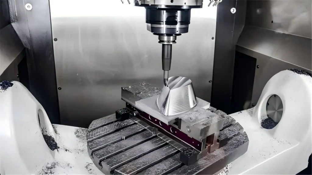
Zinc remains a favorite for complex, thin-walled geometries because it fills fine details with less energy. Copper is highly conductive and fully recyclable, making it ideal for electrical and thermal parts without losing strength. Selecting the alloy is a supplier decision we guide you through, matching material properties to your application instead of pushing a one-size-fits-all option.
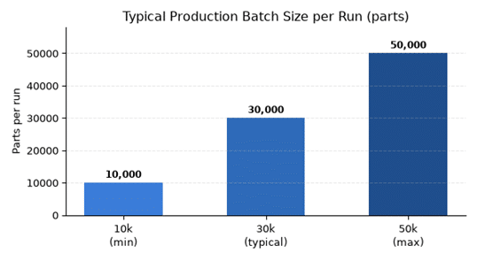
Clamping force and shot control are tuned per job. We monitor injection speed, pressure, and cooling time to minimize porosity and lift mechanical strength. Batch sizes typically span 10,000 to 50,000 parts, so the mold must stay dimensionally stable across the entire run—not just on the first hundred pieces. Heavier structural castings simply need more tonnage, and our 2000T machines handle large parts that smaller shops cannot. We verify stability with in-process sampling rather than end-of-line inspection alone.
| Alloy | Key advantage | Typical use |
| Aluminum | Lightweight, heat-resistant (wall 0.8 mm) | Electronics, lighting, automotive |
| Zinc | Fine detail, energy-efficient | Complex thin-wall parts |
| Copper | Conductive, fully recyclable | Electrical & thermal parts |
Table 2. Die casting alloy selection guide.
Matching Alloy to Application
Choosing wrong costs time. Aluminum suits lightweight structural parts; zinc excels at fine detail; copper wins on conductivity—picking the right one early keeps your tooling investment safe.
How Does MORELUX Manufacture Precision Die Cast Molds at Scale?
Tooling hands off to casting, then to finishing. After the die casts the part, roughly 80% of components move to CNC machining, where we hold ±0.01 mm and drill holes as small as 1 mm. A 24/7 machining center keeps lead times tight for automotive die casting programs that cannot afford delay.

Surface treatment closes the loop: anodizing builds a roughly 15-micron oxide layer for corrosion resistance, and finishing typically reaches below Ra 0.8 µm. All processes use RoHS-compliant materials. Before shipment, each batch passes X-ray and dimensional checks, with leak testing where specifications demand it. On our clean assembly lines we can build up to 5,000 units per day, with torque and electrical-continuity checks on every batch.
Our integrated, one-stop flow—tooling, casting, machining, finishing, assembly—means you work with a single custom manufacturer rather than juggling multiple vendors. For B2B buyers, that means shorter lead times, consistent quality, and a supplier who owns the whole chain from die cast mold to finished component. That single-point accountability is why procurement teams treat us as a long-term factory partner, not just another quote on a spreadsheet.